Kontrol Sistemleri · Dijital ders notu
Positive feedback root locus, lead/lag compensators
- Ders
- Kontrol Sistemleri (ELEC322)
- Dönem
- 6. Dönem · 2023–2024 Bahar
- Biçim
- PDF · 13 sayfa · 0,5 MB · el yazısı görünümlü LaTeX
- Orijinal not
- Control-Systems-lecture-12.pdf
The digital notes were created from the handwritten notes with the help of Claude (Anthropic); they are meant as a supplementary resource and may contain errors. Always rely on the original notes and the official course materials.
Bu notta neler var?
- Positive Feedback architecture
- Compensator design
- Adding poles
- Lead compensator: zero is closer to jω axis
- Lead lag compensator
Notun metni
Düz metin olarak göster (formüller ve çizimler yoktur)
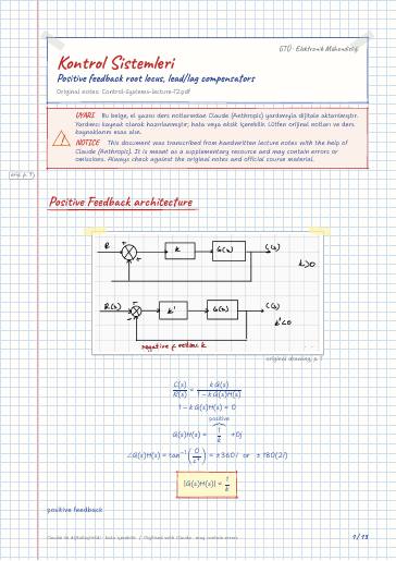
Positive Feedback architecture
(2) Departure angles from complex poles
arrival '' to complex zero
departure angle = 360 +Σ phase of c.c pole w.r.t. other poles
-Σ phase of c.c pole w.r.t. other zeros
Positive feedback system
To find characteristic equation
if its negative feedback
specific `` k '' which renders the system unstable
4 seperate roots of ch.e.q.
Its unuseless itself so we have to add a pole
by adding poles the locus plot move to right, systems get more unstable. (lag compensator)
System get more unstable - slower! ( t_s )
More accurate by adding integrator
lag compensation, The output angle is less than input
pulls the root locus plot to the left
more sensitive to noise
The output angle is more than the input angle
its leading output
lead laging compensator
Series/parallel compensation
Lead compensator: zero is closer to jω axis
if α>1 ⇒ lag compensator
Lead lag compensator
Dominant pole =-3+2j → lead compensator
Steady state error =10% (step input) → lag compensator
k give dominant pole